MSI MEG Z590 Ace Motherboard Review: Premium Rocket Lake with TB4 and 4x M.2
by Gavin Bonshor on May 26, 2021 1:00 PM ESTPower Delivery Thermal Analysis
A lot more focus has been put on power delivery specifications and capabilities, not just by manufacturers but as a result of users' demands. In addition to the extra power benefits from things like overclocking, more efficient designs in power deliveries and cooling solutions aim to bring temperatures down. Although this isn't something most users ever need to worry about, certain enthusiasts are bringing more focus onto each board's power delivery. The more premium models tend to include bigger and higher-grade power deliveries, with bigger and more intricate heatsink designs, with some even providing water blocks, while others are spending more just to make sure the most efficient parts on the market are being used.
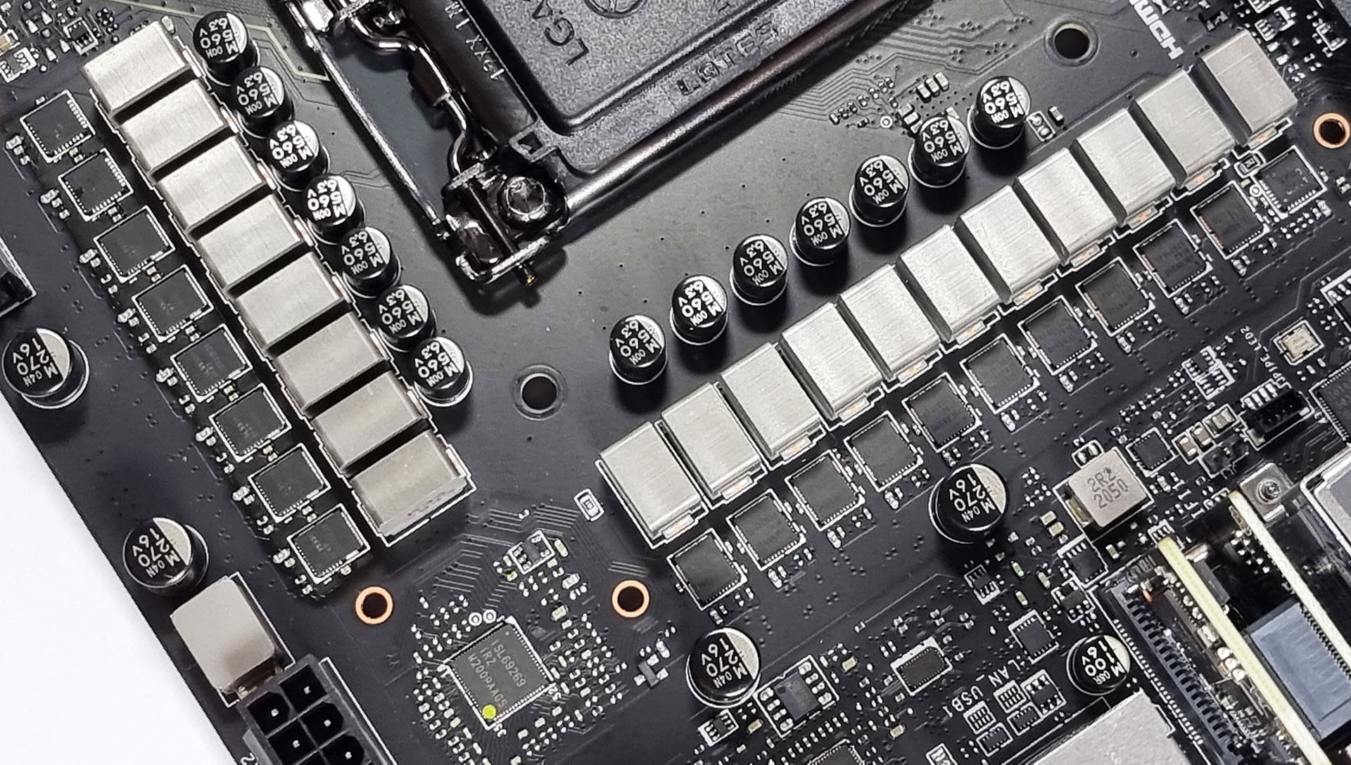
The 18-phase power delivery on the MSI MEG Z590 Ace (operating in 8+2)
Testing Methodology
Our method of testing is if the power delivery and its heatsink are effective at dissipating heat. We do this by running an intensely heavy CPU workload for a prolonged method of time. We apply an overclock which is deemed safe and at the maximum that the silicon on our testbed processor allows. We then run the Prime95 with AVX2 enabled under a torture test for an hour at the maximum stable overclock we can which puts insane pressure on the processor. We collect our data via three different methods which include the following:
- Taking a thermal image from a birds-eye view after an hour with a Flir Pro thermal imaging camera
- Securing two probes on to the rear of the PCB, right underneath CPU VCore section of the power delivery for better parity in case a probe reports a faulty reading
- Taking a reading of the VRM temperature from the sensor reading within the HWInfo monitoring application
The reason for using three different methods is that some sensors can read inaccurate temperatures, which can give very erratic results for users looking to gauge whether an overclock is too much pressure for the power delivery handle. With using a probe on the rear, it can also show the efficiency of the power stages and heatsinks as a wide margin between the probe and sensor temperature can show that the heatsink is dissipating heat and that the design is working, or that the internal sensor is massively wrong. To ensure our probe was accurate before testing, I binned 10 and selected the most accurate (within 1c of the actual temperature) for better parity in our testing.
To recreate a real-world testing scenario, the system is built into a conventional desktop chassis which is widely available. This is to show and alleviate issues when testing on open testbeds which we have done previously, which allows natural airflow to flow over the power delivery heatsinks. It provides a better comparison for the end-user and allows us to mitigate issues where heatsinks have been designed with airflow in mind, and those that have not. The idea of a heatsink is to allow effective dissipation of heat and not act as an insulator, with much more focus from consumers over the last couple of years on power delivery componentry and performance than in previous years.
For thermal imaging, we use a Flir One camera to indicate where the heat is generated around the socket area, as some designs use different configurations and an evenly spread power delivery with good components will usually generate less heat. Manufacturers who use inefficient heatsinks and cheap out on power delivery components should run hotter than those who have invested. Of course, a $700 flagship motherboard is likely to outperform a cheaper $100 model under the same testing conditions, but it is still worth testing to see which vendors are doing things correctly.
Thermal Analysis Results
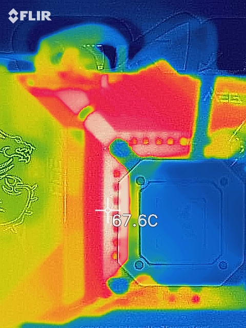
We measured 67.6ºC on the hottest part of the CPU socket during our testing
The MSI MEG Z590 Ace has a large 18-phase power delivery split into a sixteen-phase setup for the CPU, and two power stages for the SoC. The CPU section includes sixteen Intersil ISL99390 90 A power stages with eight Intersil ISL6617A doublers, while the SoC section is using a pair of Renesas RAA220075 75 A power stages. Controlling the power delivery is an Intersil ISL69269 PWM controller which is operating at 8+2. Cooling the power delivery is a pair of weighty and well-crafted heatsinks, which are connected by a single heat pipe. Attached to the heatsinks is the large metal rear panel cover, which should also add some additional cooling properties in systems with good passive airflow. The heatsinks themselves have deep channeled fins that are designed to direct and catch passive airflow when installed into a chassis.

Looking at our VRM thermal testing results for Z590, the MSI MEG Z590 Ace performed reasonably well all things considered. We observed power delivery temperatures of 69ºC from the integrated thermal sensor, with temperatures of 73 and 75ºC respectively with our pair of K-type thermocouples. Typically when testing Z590, especially on the GIGABYTE models, we've observed hotter power planes than the power delivery components themselves, but this is a different case with the Ace, which shows the heat isn't just being dumped into it, with pretty decent heat dissipation. The design of the 16+2 power delivery which is technically operating at 8+2, and the combination of the large heatsinks look to be operating with good efficiency and is taking the heat away effectively.
Overall the MSI MEG Z590 Ace performs well in our thermal VRM testing and is nearly on par with the ASRock Z590 Taichi, which is using active cooling as opposed to passive on the Ace.


11 Comments
View All Comments
TheinsanegamerN - Wednesday, May 26, 2021 - link
That's a LOTTA money for a motherboard without 10Gbe and limited to either 10 coffee lake cores or 8 rocket lake cores.YB1064 - Thursday, May 27, 2021 - link
Yes, I agree. No 10GbE in a premium board = no buy!ballsystemlord - Thursday, May 27, 2021 - link
I also agree. I can't order even 0.5G Ethernet but I defiantly need that 10GbE port!lmcd - Friday, May 28, 2021 - link
Aside from defiantly being unable to spell, the point of 10G Ethernet is connection to a local NAS, among other things.kpb321 - Wednesday, May 26, 2021 - link
The Mini DP in for supporting the USB-C display port alt mode with a discrete video card has always felt like a pretty clunky solution. That's why I've always felt like that was much more useful on laptops, SFF etc where there is no support for changing a dedicated GPU and you just build that into it. I wonder if they could built Display port signaling into the PCI-E slot using some reserved pins or an extra section of connectors or something like that to make it simple with a dedicated GPUTheinsanegamerN - Wednesday, May 26, 2021 - link
You can already do video signaling through PCI-E. That's how laptop GPUs have worked ever since the first iterations of optimus.Jorgp2 - Thursday, June 3, 2021 - link
Pretty sure it's actually built into windows nowadays.damianrobertjones - Thursday, May 27, 2021 - link
"with a flagship motherboard model costing nearly double that. It comes down to..."Greed.
Questor - Thursday, May 27, 2021 - link
All this connectivity and still a shortage of PCI express lanes.GNUminex_l_cowsay - Thursday, May 27, 2021 - link
I think the next high end motherboard review needs to have a feature comparison table. Post time and idle power are impossible to interpret without knowing what is on the board and these high end boards have a lot of things.